Præludium
My quest for the Almighty Subwoofers really started when I as a teenager heard a rock band play. The band had a huge bass guitar amplifier, and the clean punch from this, far from anything I'd ever heard, made a deep impression on this author. The next shock was to hear a system a freaked-out farmer living nearby had build. He took an old Seas speaker system (type 60, I think is was called) and put it into enormous transmission line enclosures. They had reasonable output down to about 25 Hz, and one of his direct-cut church organ records made me order a pair of his speakers immediately.
Later, when I was studying to become an audio technician, I naturally got into DIY (in DIY audio was successful - computers later became my proffession). My first DIY speakers were a pair of 3-way transmission lines, using KEF B-139 bass drivers (like the KEF Bailey). This system was later replaced by a much simpler and better sounding two-way bass-reflex system with a 6,5-inch woofer. Since then I've used the two-way concept in many different variations, ending up in the main system I use now. Common to them all were a lower cut-off starting at 40 Hz. On the way I began to really miss the 20-25 Hz response I had with my transmission lines, and the search for a dedicated subwoofer soon materialized.
My first attempt at a subwoofer was a single mono sub utilizing a Seas P21REX 8-inch driver in a 130 liter vented box. Of obvious reasons this did not work very well. The cone sure moved, but the 20 Hz tone could not be heard through the noise and distortion.
The disappointment from the first try lasted a while, so it took me some time to heat up the jig-saw again. New experiments were done with two (stereo) subwoofers, using 10-inch drivers (ScanSpeak 25W7564). The audible result was good, but the low sensitivity of the system, only 83 dB at 20 Hz, and limited SPL capacity made me expand the system by using two drivers in each box. This system became the "REAL Subwoofers", also presented on the SBP. I used them for two years, the longest period a speaker system had ever served in my stereo without any modifications on the way.
Postludium
The following is intended as a follow-up on the "REAL Subwoofers". I suggest you read that article first.
The "REAL Subwoofers" had been a very successful project, but several facts made me realize that far better performance was possible. I set the following goals for the new system design:
Driver selection
The drivers I chose to use in the new subwoofers were, naturally, selected and purchased before the enclosure was designed. The enclosure design was a rather fast process, and enclosure building lasted for only three weeks.
To find the right driver however, was not easy. I made many low-frequency simulations and investigations on normal "hi-fi" drivers, only to conclude that the driver I wanted was nonexisting. No driver, or combination of drivers, could satisfy my requirements.
A friend of mine talked much (he still does) of the SPL performance and power capacity of proffesional drivers, and he must have influenced me to look in the "pro" direction. My friend lent me some JBL and RCF datasheets, and I started to do low frequency simulations. I was really stunned! As an example, the RCF L18P300 18-inch can play 120 dB at 20Hz in a vented box without exeeding Xmax.
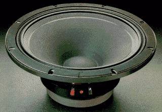
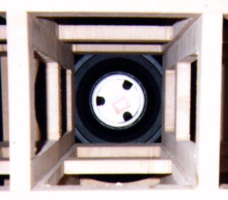
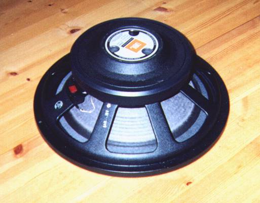
The driver I found most favourable for my specific requirements was the JBL 2226G (15-inch). The 2226's distortion measurements is very impressive below 150 Hz, even lower than JBL's 18-inch drivers at the same SPL. The magnet system is carefully designed for low distortion, and the cone is quite good to be paper-based. Thermal power capacity is an incredible 600 W continous pink noise, which will insure no power compression at normal listening levels. The clever construction of the surround actually reduces the moving area of the surround. The aluminium frame is excellent, especially the extremely solid surround. Judged by technical parameters, the JBL 2226 is almost impeccable. It is surprisingly low priced, about half of what a "car-fi" 15-inch woofer costs (JBL 2226 costs NOK 2940 in Norway, equal to about US$ 400).
At first I was very sceptical to how a proffesional woofer would sound. I'd heard PA systems using JBL 15-inch drivers as midranges, and they did not sound much like hi-fi. However, those system used the drivers in a frequency range I would not use them. An other consideration was the quality of the cone. A 335 mm paper cone is not expected to be very stiff, but JBL proved to know what they are doing in this area as well. The Norwegian JBL Pro Audio representative (Lydrommet AS, thanks to them) kindly let me take a closer look at a JBL 2226, and finally I decided to buy two of them. I chose to use the 4 ohm version, as this has the highest voltage sensitivity. If you have an amp with high output voltage capacity, the 8 or 16 ohm version may be your choice.
The following section is stolen from the JBL data sheet (there are no copyright notices on their datasheets!), with some changes applied.
JBL 2226 G/H/J - 380 mm Low Frequency Transducer
 (Click the image for a larger view.)
Key features:
Specs:
| Nominal diameter | 380 mm |
| Rated Impedance | 4/8/16 ohm (G/H/J) |
| Power Capacity | 600W AES continous pink noise (AES standard, 50-500 Hz) |
| Sensitivity | 97 dB SPL / 1W / 1m (2V @ 4 ohms (G), 2.183V @ 8 ohms (H), 4V @ 16 ohms (J)) |
| Frequency Range | 30-2.5 kHz (-10 dB) |
| Power Compression | 0.7 dB at -10 dB power (60W) 2.5 dB at -3 dB power (300W) 4.0 dB at rated power (600W) Power compression is the sensitivity loss at the specified power, measured from 50-500 Hz, after a 5 minute AES standard pink noise preconditioning test at the specified power |
| Distortion | 2nd harmonic <1% @ 60W, 50-500 Hz 3rd harmonic <1% @ 60W, 50-500 Hz |
| Highest Recommended Crossover | 1200 Hz |
| Recommended Enclosure Volume | 85-285 l |
| Effective Piston Diameter | 335 mm |
| Maximum Excursion Before Damage | 40 mm (p-p) |
| Minimum Impedance | 3.0 ohms ±10% @ 25 ºC (G) 6.0 ohms ±10% @ 25 ºC (H) 12.0 ohms ±10% @ 25 ºC (J) |
| Voice Coil Diameter | 100 mm |
| Voice Coil Material | Edgewound aluminium ribbon |
| Voice Coil Winding Depth | 19.05 mm |
| Magnetic Gap Depth | 8.1 mm |
| Magnetic Assembly Weight | 6.8 kg |
| B*l factor | 13.5 N/A (G) 19.2 N/A (H) 27.1 N/A (J) |
| Effective Moving Mass | 0.098 kg |
T/S parameters (after break-in)
| Fs | 40 Hz |
| Re | 2.5 ohms (G) 5.0 ohms (H) 10.0 ohms (J) |
| Qts | 0.31 |
| Qms | 5.00 |
| Qes | 0.33 |
| Vas | 175 l |
| Sd | 880 cm² |
| Xmax | 7.6 mm |
| Vd | 689 cm³ |
| Le | 0.92 mH (G) 1.75 mH (H) 3.5 mH (J) |
| no | 3.3% |
| Pe | 600 W |
Frequency Response and Impedance Curves
 Measured
in 280 l closed box, hemispherical free-field, on axis. Dotted line 45
degrees off axis. Dashed curve 140 l / 40 Hz vented box. Impedance measured
in free air. (Click the image for a larger view.)
Measured
in 280 l closed box, hemispherical free-field, on axis. Dotted line 45
degrees off axis. Dashed curve 140 l / 40 Hz vented box. Impedance measured
in free air. (Click the image for a larger view.)
Distortion curves
 Distortion
levels raised 20 dB. Measured at 60 W, 1 meter in 280 liter closed box.
(Click the image for a larger view.)
Distortion
levels raised 20 dB. Measured at 60 W, 1 meter in 280 liter closed box.
(Click the image for a larger view.)
JBL's distortion measurement show signs of cone breakup modes above 150 Hz causing an increase in distortion. Of this reason high performance is only to be expected at low frequencies. I recommend a maximum crossover at 150 Hz. In less critical applications 300 Hz may be an acceptable crossover frequency.
Also note that the distortion is measured at a very high input power, 60W. Distortion measurements on "hi-fi" drivers are usually carried out at only 2-5 W input.
The JBL 2226 is extremely noise-free, meaning there are virtually no rattling or "breathing" at large cone excursions, an otherwise very common phenomenon.
All JBL drivers share this same pecularity; the black terminal is positive and the red negative, or as JBL puts it: "Positive voltage on BLACK terminal gives forward diaphragm motion". The terminals look cheap, but they work surprisingly well.
Don't the JBL 2226 have flaws that should be corrected by modification? Well, I have to admit that any limitations are hard to find!
System design
The prime design goals of a subwoofer are quite clear: The frequency response should be flat from at least 20 Hz up to 100-150 Hz where it will cross over to the main system. It should be able to produce sufficient SPL levels at any frequency in its working range and possess low distortion and colouration. Further the system must have reasonable efficiency, and may not be excessively large. Let's see how these target parameters are met in the system presented here.
I set the maximum enclosure volume to 200 liters (it later proved to have an acoustic volume of ca. 220 liters), and some limits on the proportions. The height should not be greater than allowing placement of a midrange/tweeter system on top, and the depth not more than 90 cm. An enclosure of this size is indeed large, but not beyond acceptable limits in my opinion.
I had already decided what box type to use, but let's just look at the different alternatives. A horn with 20 Hz cut-off is absolutely not possible within my size restriction. Open baffle systems require enormous cone areas to produce any usable SPL because of the massive acoustic cancellation from the driver's rear side, unless the baffle is of infinite size. Let's jump over that too. More commonly utilized acoustic loading are closed box, vented box, bandpass and various passive radiator systems. Let's eliminate the passive radiators first of cost reasons. A15-inch or preferably larger passive radiator of high quality is not at all inexpensive. Bandbass boxes leaves very little flexibility in choosing upper crossover frequency, and they are prone to sound rather honky. A closed box in general may have 6 dB lower sensitivity and a dramatic 10 dB less linear SPL capacity than a vented box. A closed box of the same volume as used here with the same driver have 13 dB less maximum SPL at 22 Hz, and 10 dB less at 30 Hz! This explains in part why closed box subwoofers don't work particularly well. Obviously, vented box is my choice.
A vented system's cut-off rate is very high, usually 4th order (24 dB/octave), which make the response fall off rapidly below cut-off, which happens somewhere near the tuning frequency. Tuning the vented box at a too high frequency will not allow the system to be equalized flat to 20 Hz. In addition, the driver's cone excursion greatly increases below the tuning frequency, and the distortion increases tenfolds (!). Going in the other direction, a low tuning frequency will decrease the system's sensitivity, and require greater cone excursion above the tuning frequency, also reducing the maximum linear SPL capacity.
I found tuning at 24 Hz to be an acceptable compromize. The important 40-100 Hz range shows very satisfying efficiency, and it is still possible to equalize the system flat to 20 Hz without disasterous results regarding cone excursion or input power requirements. With the system equalized flat, the cone excursion for a given SPL remains almost constant over the octave span from 45 Hz down to 22 Hz. This is remarkable indeed. A closed box would show a 12 dB/octave increase in cone excursion, causing the cone excursion to increase a dramatic four times from 45 to 22 Hz.
My desires for 110 dB output without exeeding 1/2 of driver Xmax are very close to being satisfied down to about 22 Hz. The linear SPL capacity is greater than 115 dB above 22 Hz.
The dotted red line on this graph shows SPL with cone excursion
at 1/2 of Xmax, limited by maximum input power (600W):
The dotted red line on the graph shows SPL with cone excursion
at Xmax, limited by maximum input power (600W):
Damage limited SPL (at 40 mm peak-to-peak cone excursion) is impressing,
see the graph below. I've set the input power to 4000W in this simulation,
and I'm quite convinced that the driver can survive this power in short
peaks. Power compression and other effects will certainly reduce the real
output, but this simulation is no matter what very convincing. In other
words; headroom in normal applications is no problem.
The simulation of the acoustic response of the unequalized system does'nt look like a subwoofer at all (the red line on the image below). I chose to try equalizing the system flat (OK, it's -2 dB) to 20 Hz, even if the cone excursion and distortion starts to run wild below 22 Hz. First I added a 2nd order high-pass filter at 16 Hz with a Q of 1.3. This filter will, in addition to flatten the response, effectively cut off subsonic input below 16 Hz. The response now looks like the blue line. The next task is to get rid of the rise above 40 Hz. I do this by adding a 1st order filter at 60 Hz. This response resulting from this, the black line, falls off smoothly above 100 Hz. Since I cross over at 100 Hz, this only means I get a steeper cut-off. Crossing at 150 Hz would only require an adjustment of the filter Q. I'll get back to the filter later in this article.
JBL 2226G at 2.83V input (1W @ 8ohms)
2226H (8ohm) will produce 3 dB less output at 2.83V input and 2226J (16 ohm) will produce 6 dB less ouput.
Note: All simulations shown in this article are using
half-space free-field acoustic conditions.
Enclosure
 My
enclosure requirements were easy to accomplish, by recycling previously
used ideas. My current main system have enclosures made of sandwiched walls
with internal bracing in addition. The sandwich consists of three layers
of HDF boards, filled with sand inside. The sand filling is done by making
a large cut-out in the middle HDF board, and filling the cavity with sand
through a small hole, after the three boards are glued together. An enclosure
build this way is very heavy and extremely free of colouration. I decided
to build all enclosure walls of sandwich if possible, and use heavy internal
bracing that should support the driver as well. Besides this, the enclosure
shares design ideas with my previous subwoofer project. I ended up with
a sandwich consisting of three layers of 12 mm HDF. This construction is
a good comprimise between acceptable enclosure weight and low colouration.
The internal bracing was done with 19 mm HDF. The resulting enclosures
are 80x70x60 cm (depth/height/width) and weighs about 160 kg each (excluding
the driver). Their performance is very satisfying; there are virtually
*NO* signs of enclosure vibration. The image shown is is a 3-D drawing
of the enclosure, with one side removed. The driver's magnet is supported
by the internal bracing. The shaded parts are sandwiched boards, and the
rest 19 mm HDF. All parts are glued, I never use screws!
My
enclosure requirements were easy to accomplish, by recycling previously
used ideas. My current main system have enclosures made of sandwiched walls
with internal bracing in addition. The sandwich consists of three layers
of HDF boards, filled with sand inside. The sand filling is done by making
a large cut-out in the middle HDF board, and filling the cavity with sand
through a small hole, after the three boards are glued together. An enclosure
build this way is very heavy and extremely free of colouration. I decided
to build all enclosure walls of sandwich if possible, and use heavy internal
bracing that should support the driver as well. Besides this, the enclosure
shares design ideas with my previous subwoofer project. I ended up with
a sandwich consisting of three layers of 12 mm HDF. This construction is
a good comprimise between acceptable enclosure weight and low colouration.
The internal bracing was done with 19 mm HDF. The resulting enclosures
are 80x70x60 cm (depth/height/width) and weighs about 160 kg each (excluding
the driver). Their performance is very satisfying; there are virtually
*NO* signs of enclosure vibration. The image shown is is a 3-D drawing
of the enclosure, with one side removed. The driver's magnet is supported
by the internal bracing. The shaded parts are sandwiched boards, and the
rest 19 mm HDF. All parts are glued, I never use screws!
It is necessary to use acoustic damping inside the enclosure. I've covered the side walls, top and bottom (the port, really) and the top 3/4 of the back with 75 mm fiberglass (building insulation). It is important to avoid obstructing the port. Damping of the port must not be done, even though the very long port has strong resonant modes at 250 Hz and above. Since this is safely above the crossover frequency, it does not cause any audible problems. The port area is also large enough to avoid turbulence noises at normal listening levels.
Mounting screws are included with the JBL drivers, but I do strongly recommend using hexagon or torx screws instead. The JBL-supplied screws are simply too weak. Not one of my screws survived mounting the driver!
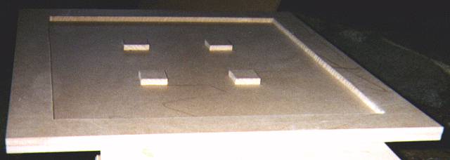
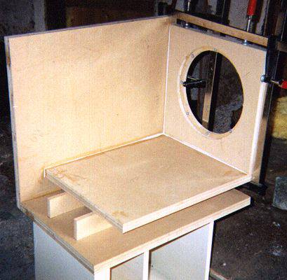
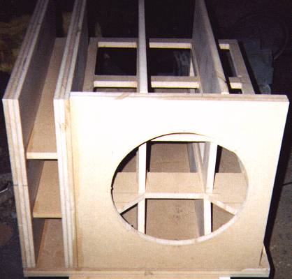
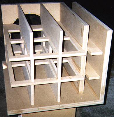
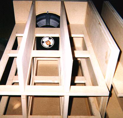
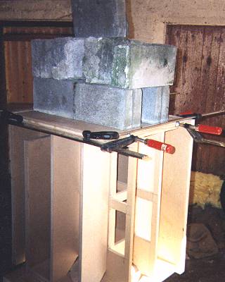
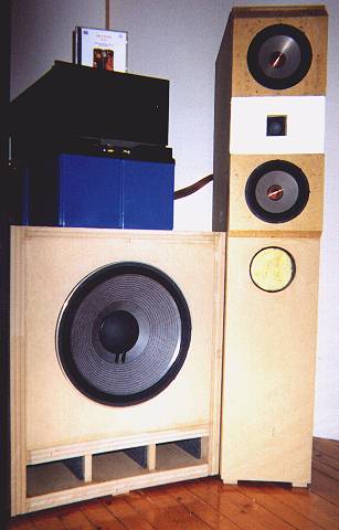
I took some photos during the building process. Links to the images follow below. The images may give a better idea of what the enclosures looks like. The photos are taken with a Kodak Fun Gold camera with flash (camera and film in one piece, REAL Crap!), and scanned on a far from high-end scanner, and then saved with 30% JPEG compression to reduce the file size. Needless to say, the quality could have been better.....
Filters
Successful employment of a passive filter in a subwoofer is highly unrealistic. Creating only a crossover function at 100-150 Hz with a 4th order slope might be within reach, but you can just forget about a lower crossover frequency or equalizing. The reasons for this is the difficult impedance of the driver in the cross-over range, and the extremely large component values needed. A successful result requires extensive impedance correction, which will lower the system impedance. Passive EQ will also greatly lower the efficiency. In the end, the system becomes virtually impossible to drive. Active filters is the only solution!
The filter is EQ'ing the system as I have described in a previous section, and crossing at 100 Hz with 4th order Linkwitz-Riley slope (IMHO, the only correct filter type). The filter block schematics is shown below. The filters are best made up with op-amps, I use the LM837 (quadruple). LM837 is designed for audio use, has very good data and (best of all) is not expensive. Sounds good too...
 The
first two sections are the equalizer. The two last 2nd order filters are
in combination a 4th order Linkwitz-Riley filter. The equalizer's roll-off
above 100 Hz creates a steeper total roll-off than a 4th order function,
but this does not cause any phase problems in the crossover region, as
the 180 degrees phase shift is located exactly at 100 Hz. The graph to
the left shows a simulation of the equalized frequency response including
the crossover (solid line) compared to the 4th order Linkwith-Riley function
(dotted line).
The
first two sections are the equalizer. The two last 2nd order filters are
in combination a 4th order Linkwitz-Riley filter. The equalizer's roll-off
above 100 Hz creates a steeper total roll-off than a 4th order function,
but this does not cause any phase problems in the crossover region, as
the 180 degrees phase shift is located exactly at 100 Hz. The graph to
the left shows a simulation of the equalized frequency response including
the crossover (solid line) compared to the 4th order Linkwith-Riley function
(dotted line).
The main system used with the subwoofer must be crossed with the same filter slope as the sub. The main system should also have approx. flat response at least one octave below the crossover frequency in order to get a flat summed response using a by-the-book 4th order filter for the main system. Using the sub with "satellites" (small speakers) with its cut-off above 50 Hz will require a different filter. The best way to design this is by simulation of the whole system in a proper crossover software (The only ones I can recommend is CALSOD or LEAP).
My own solution is using a 2nd order filter at 100 Hz with quite high Q for the main systems. Their acoustic response falls off 12 dB/octave below 100 Hz (closed box) with low Q at resonance. The sum is a 4th order roll-off with -6 dB at 100 Hz, and perfect phase correlation at 100 Hz (180 degrees shift for both the sub and main system).
More filter details
Acoustic measurements
Can measurements give us any clue of what a speaker sounds like? The most flawed systems can easily be selected out by measuring key parameters like frequency response and distortion. However, no speaker sound the same and no speaker measure the same. The speaker with perfect technical data does not exist, and probably never will, but a speaker that measure good usually sounds good too.
I performed measurements of frequency response and distortion on the finished subwoofers to ensure that the theory behind the system was not too far from reality. The measurements were done with a Techron TEF-20 analyzer using a Brüel & Kjær 4007 microphone, both kindly provided by an acoustic consultant, Lars Tofastrud, that happens to be a good friend of mine (VERY convenient...)
Measuring a speaker's low frequency response in a normal room is in general totally impossible! This is because the room's acoustics totally dominate the measurement. The room's resonant modes will disturb even a near-field measurement. A low-frequency measurement should be executed at a large open plane outdoors. Dragging 160 kg of speaker enclosure out in the corn field in december did not tempt me too much, so I decided to try indoors. The TEF's TDS (Time Delay Spectrometry) measurement technique allows you to isolate the speaker-response from the room's response, but on the downside this reduces the resolution at low frequencies, so a suitable compromize is necessary. About 100 ms of room decay (after the direct signal from the speaker) is included in the first three measurements shown (100 ms Time Resolution in the TEF TDS parameters). Measurements were done with the filter and equalizer included.
My room has its major resonances (both standing wave modes and structural resonances) below 100 Hz placed at 19, 23, 27, 34, 46, 65 and 80 Hz (I've measured this with the TEF). These can be spotted on the measurements below, especially the 19, 23 and 65 Hz modes stand out. No smoothing is applied on the response curves (no fakes!).
Near-field on the driver:
Near-field on the port (inside the port actually):
Near-field midways between the port and driver. The dip at 200 Hz is probably caused by a floor reflection.
The next is a measurement I did at my listening position (2.2 meters) at the same amplifier output as the above measurements. I used 500 ms time resolution on the TEF (500 ms of room decay is included in the frequency response) to capture the most significant room response. This looks extremely bad, but is in fact much better than obtainable in an average room. My room is quite heavily trimmed acoustically and its bass sounds superior to most other listening rooms. Even so, it still has a very slow decay below 50 Hz (about 1s RT60 at 23 Hz!) This measurement is indeed coloured by the slow decay.
Below is the first 600 ms of room decay that causes the rugged response shown above, measured in one rear corner of the room. Note that many strange things happens to the room modes after 200-250 ms. It's a wonder that music can sound natural in such an acoustic environment, when the room reverb changes pitch during decay. (I could write hundreds of pages on this.....)
Distortion measurements are a little easier, as the room's response will have less effect on the result. Even so, I measured in the near field (about 10 cm from the driver cone). The amp output is at a level that produces 96 dB SPL at 1 m (the amp output voltage varies a great deal with frequency because of the crossover and equalizer).
This measurement really shows what happens below the tuning frequency in a vented box! As you can see, the THD is almost 25% below the tuning frequency, but less than 1,5% at any frequency above. The distortion components are mainly of 3rd and 4th order.
Impedance correction
Impedance correction of the speaker is important to the amplifier. No amplifier sound better with a strongly reactive load than with a less reactive load. The point in impedance correction is to flatten both the impedance phase angle and magnitude. This is usually done with L-R-C filters connected parallell to the input terminals. It is possible to achieve a perfectly flat impedance this way, but the drawback is the need for extremely large value capacitors and inductors. There is no way out of using electrolytic capacitors and cored, thin-wire inductors. Using components of such quality is disasterous to sound quality, even in impedance correcting filters.
I simply use a resistor in parallel! This solution will not flatten the impedance as much, but will provide an enjoyable improvement. By selecting a proper resistor quality, the resistor in it self will not detoriate the sound quality. I use a 10 ohm "Kool-Pak" (Caddock MP930), which is a thick-film resistor in a TO-220 housing. The power capacity of the Kool-Pak is 30 W when mounted on a proper heat sink, sufficient for most applications. The audible result of impedance correction is a tighter bass that also sounds deeper and better defined.
Amplifier requirements
The good efficiency of the JBL 2226 driver will not make calls for high-power amplifiers. In fact, the system's efficiency in the bass-range (40-100 Hz) is higher that most speakers, who rarely exceeds 90 dB. Crossing at 100 Hz will also leave nearly 90% of the power in music to the main system.
My own main system has a sensitivity of ca. 92 dB. Measurements with real music on this system show that the power requirement for the sub is only 1/10 of the main system. I use 80W/4ohm amps for the main systems, and a 2x20W/4ohm amp for the subs. I don't have any records that make the sub's amp clip before the main systems' amps. 20W on these subs are in fact enough power to knock your socks off!
Sound
The first listening tests were quite a shock to me. I had certain ideas of how it would sound compared to my previous system, but the result was very different from what I had expected. It took me some time to get used to it, and realize how great an improvement it really was. Their sound quality is absolutely outstanding compared to all other subwoofers I have heard, even compared to high-end headphones. They reproduce every sound in a recording without any sign of loosing control or definition. Powerfull transients can really pound on your chest, but there is no car-fi-boom-box rumble, only ultra-tight punch.Virtually no speakers can reproduce a continous low frequency signal, like a church organ pedal, without loosing the grip after 100-200 ms. The tone starts like a soft transient, and then dies a little in intensity. This does not happen with these subwoofers, they never run tired. At first it was also very surprising to discover the huge differences that really exists between different recordings in the low frequency ranges. The subwoofers have very good definition, and display these differences with all possible clarity.
Stig Erik Tangen
1.1.97