Mark F. Davis
Dolby Laboratories Inc.
100 Potrero Ave.
San Francisco, CA 94103, U.S.A.
Reproduced by permission of the Audio Engineering Society, Inc.
Presented at the 95th Convention, 1993 October 7-10
This paper describes the operation of the AC-3 multichannel adaptive transform coder. Coding a multiplicity of channels as a single entity is more efficient that coding individual channels, permitting a lower net data rate. The major processing blocks of the AC-3 coder are presented and discussed, along with the underlying psychoacoustic principles. Strengths and limitations of the coding techniques are cited.
I. INTRODUCTION
AC-3 is a high-quality, low-complexity multichannel audio coder. By coding a multiplicity of channels as a single entity, it is able to operate at lower data rates for a given level of audio quality than an ensemble of equivalent single channel coders.
Although AC-3 algorithms are independent of the number of channels coded, current implementations have standardized on the SMPTE-recommended 5.1 channel arrangement: five full bandwidth channels representing Left, Center, Right, Left-Surround, and Right-Surround; plus a limited bandwidth low-frequency Subwoofer channel. AC-3 conveys this channel arrangement with a high degree of transparency at data rates as low as 320 Kbps.
The following sections describe the AC-3 coding algorithm, identify its primary processing elements, and discuss the underlying psychoacoustic mechanisms involved.
II. PROCESSING OVERVIEW
Like the AC-2 single channel coding technology [1] from which it derives, AC-3 is fundamentally an adaptive transform-based coder using a frequency-linear, critically sampled filterbank based on the Princen-Bradley time domain alias cancellation (TDAC) technique [2]. The primary advantage of filterbank-based coding is that signal components and corresponding quantization noise components (intended to be masked) are kept within a critical bandwidth of one another, deriving maximal benefit from the masking characteristics of the human ear, and minimizing the resulting datarate needed for perceptually noise-free coding.
In the presence of (wideband) transients, the transform block length of the filterbank can be dynamically reduced to contain quantization noise to a small temporal region about the transient.
A flexible bit allocation technique capitalizes on the multiplicity of channels by assigning bits across frequencies and channels as needed, from a common bit pool, while taking into account both intra- and inter-channel masking effects. Further coding gain is realized as needed by separating and independently coding high frequency carrier and envelope information.
The following sections describe the major encoder and decoder processing steps in greater detail.
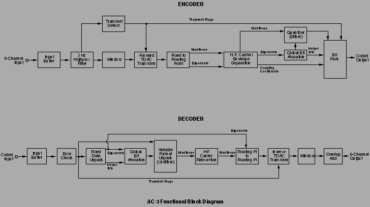
III. MAJOR ENCODER PROCESSING BLOCKS
a. Input buffer
AC-3 is a block-structured coder, so one or more blocks of time domain signals, typically 512 samples per block, are collected in an input buffer from each channel before proceding with additional processing.
b. Input filtering
The encoder input signals are individually highpass filtered at about 3 Hz, to remove DC offset. The Subwoofer signal is also lowpass filtered above 120 Hz.
c. Transient detection
The filtered, full-bandwidth input signals are analyzed with a high frequency bandpass filter, to detect the presence of transients. This information is used to adjust the block size of the TDAC filterbank, restricting quantization noise associated with the transient within a small temporal region about the transient, avoiding temporal unmasking.
d. TDAC Filterbank
Each channel’s highpassed time domain input signal is individually windowed and filtered with a TDAC-based analysis filterbank. The TDAC transform is basically an FFT followed by an additional ‘twiddle’ stage; it features low computational complexity with good frequency selectivity, facilitating cost- effective hardware implementation with excellent signal performance.
Further processing is carried out on the 5.1 channel ensemble of TDAC transform coefficients, treated largely as a single entity. (Only the first few transform coefficients of the Subwoofer channel are carried forward.) Ultimately, the decoder recovers time domain signals from reconstructed transform coefficients via a TDAC inverse-transform-based synthesis filterbank. Both analysis and synthesis filterbanks are critically sampled and exact reconstructing, therefore information-lossless. Additionally, both filterbanks employ 50% block overlap, avoiding discontinuities at block boundaries. Coding gain is obtained primarily from selective quantization of the transform coefficients, which comprise the main element of the coded information. As long as the coding does not eliminate or add audible information, the decoded output will sound the same as the encoder input.
e. Conversion to floating point
Even when implemented on fixed-point DSP chips, AC-3 TDAC transform coefficients are converted to floating point representation for further processing, with mantissas having a magnitude range of 0.5 to 1.0, and corresponding exponents. This ensures that intermediate processing imposes no practical dynamic range limitations. Wide dynamic range is maintained by the input and output transforms by using intermediate stage scaling as needed. As a result, AC-3 preserves the sonic benefits of high resolution (18-22 bit) A-D and D-A converters.
The floating point data representation, particularly the presence of the exponents, also serves as a computational aid for logarithmically-oriented processes such as bit allocation.
f. Carrier precombination
In general, the average bit demand of multiple channels appears to be roughly proportional to the square root of the number of channels. If it takes 128K bps to code a single channel, on average 5.1 channels require 128*sqrt(5.1) = 289 Kbps, comfortably within the 320 Kbps minimum datarate used by AC-3. This implies most multichannel signals can be properly coded via just the flexibility of the global bit allocation technique. For high demand signals, selective precombination of high frequency carrier components is used to provide further coding gain.
This technique eliminates redundant high frequency localization information, based on the psychoacoustic phenomenon that at high frequencies the human auditory system localizes sound based principally on the *envelopes* of critical-band-filtered versions of the signals reaching the ears, rather than on the signals themselves [3]. This behavior is exploited in AC-3 by separating high frequency subband signals into envelope and carrier components, generally coding the envelope information with greater precision than the carrier information, and if necessary, selectively combining (coupling) carrier components across channels. This has minimal audible impact, since the localization information is preserved in the envelope data, and the carriers would in any case combine acoustically at the listener’s ears, producing an equivalent result.
The coded carrier information augments the exponent and mantissa arrays, while the envelope information is conveyed as an array of coupling coefficients.
This technique accurately preserves spatial and other sonic characteristics, not only of sounds from discrete sources (loudspeakers), but also of phantom images appearing between loudspeakers. It also preserves both the acoustic power of each source signal component, and the acoustic power of each speaker feed.
g. Global bit allocation
The primary advantage of unified multichannel coding is probably the ability of the allocation routine to shuttle quantization bits across channels and frequencies as necessary, to meet the shifting demands of the signals.
The AC-3 bit allocator analyzes the TDAC coefficients with respect to their (inter-) masking effects and relation to absolute hearing threshold, to compute the quantization accuracy (number of bits) required to code each mantissa. The calculation is performed globally on the ensemble of channels as an entity, using a single, common bit pool, with few if any fixed, preassigned bits.
Although allowance is made for the effects of interchannel masking, the ability of a signal in one channel to mask noise in a different channel is limited, and varies depending on the listener’s position, so the overall effect on calculated bit allocation is kept small, and in any case is restrained from inducing audible bit starvation in any channel.
Both encoder and decoder perform the same core bit allocation routine, working primarily from the TDAC exponent information; however, the decoding process is made simpler by having the encoder preserve and transmit intermediate results from its allocation calculations. This obviates the need to perform the corresponding calculations in the decoder. The encoder also has the option of sending bit allocation override information, to allow for future encoder refinements with existing decoders.
h. Quantization
The results of the bit allocation calculation are used to quantize the TDAC mantissa data. Rather than simply sending the ‘n’ most significant bits of a value, the value is scaled and offset to provide zero-centered, equal-width, symmetrical quantization levels (odd symmetrical quantization), to minimize distortion and facilitate the use of subtractive dither. Compensatory processing is provided in the decoder mantissa unpacking code to recover actual mantissa values.
The encoder can optionally dither the mantissa data in the course of quantizing it. Mode bits in the transmitted data stream indicate if dither is in use and provide synchronization information, so the decoder can subtract out exactly the same dither data in reconstructing the mantissas. The pseudo-random number generator has been designed not only to have good randomness properties, but also to produce identical results regardless of the hardware platform.
i. Data packing
The above processes convert each block of 6 channels of time signals into a series of derived arrays and scalar values, including TDAC exponents and quantized mantissas, bit allocation sidechain information, coupling coefficients, and dither flags. In the final stage of the encoding process, this information is packed into a single block, along with synchronization information, a header and optional miscelleneous and error correction information. Care is taken to pack the data in a logically causal fashion, so the decoder can unpack it.
IV. MAJOR PROCESSING BLOCKS - DECODER
a. Input buffer
The decoder, like the encoder, is block structured, and so establishes and maintains sync with the incoming datastream, collecting an entire coded block in an input buffer before proceding to decode it.
b. Error concealment
Each decoder input data block is checked for internal consistency, as well as the presence of status information from an optional external error correction processor. If an uncorrectable error condition is indicated, the decoder may reuse the last known good input block in place of the current one to conceal the error. The overlap/add nature of the signal reconstruction process renders this form of error concealment relatively benign, and a given good block can generally be repeated several times, if necessary, before extended error conditions require the decoder to either mute or, in applications such as film soundtracks, revert to using the co-existing analog soundtrack.
c. Fixed format data unpacking
Data unpacking is carried out in two stages. First, the fixed format data is unpacked, including exponents, coupling coefficients, and mode flags. Relevant portions of this data are then used by the decoder to recover the bit allocation, which is used in turn to unpack the variable format data, principally the TDAC mantissa arrays.
d. Decode bit allocation
The decode bit allocation routine is nearly identical to the corresponding encode allocator, except that it uses the transmitted intermediate results to save time, and optionally to modify the derived bit allocation as directed by the encoder. This arrangement also allows the decoder to compute the bit allocation one channel at a time, reducing decoder memory requirements.
The decoder bit allocation must exactly match that of the encoder in order for the variable format data to be properly unpacked, or chirp-like artifacts may be introduced into the output.
e. Variable format data unpacking
The recovered decode bit allocation, specifying the quantized size of each mantissa, is used to unpack the variable format data from the coded bitstream.
f. Conversion to fixed point
In preparation for the inverse TDAC transform, mantissa and exponent data are combined to reconstruct fixed point TDAC coefficients. If dither is in use, it is subtracted at this point in the process.
g. High frequency carrier reinsertion
High frequency coefficients that have been coded as carrier and envelope information are reconstructed by combining carriers with corresponding coupling coefficients.
h. Inverse Transform
Each channel’s recovered TDAC transform coefficients are inverse- transformed back to the time domain, windowed, and overlap-added to produce decoded digital time domain output signals. The Subwoofer coefficients are zero padded at mid and high frequencies before transforming, so that the Subwoofer time domain output is at the full sample rate.
V. DISCUSSION
In addition to describing the elements that make up the AC-3 coder, it is perhaps useful to point out an element quite specifically omitted, namely the use of matrixing (adding and subtracting of channels) in performing the multichannel coding/decoding. In the context of low bitrate coders, matrixing and other channel-subtractive processes have the undesirable property that quantization noise associated with a particular signal may be directed by the decode matrix to a different channel than the signal itself, thereby allowing the noise to become unmasked. The AC-3 coding process inherently preserves the codirectionality of signals and corresponding quantization noise, to maintain masking.
The absence of matrix-based processing within AC-3 in no way inhibits its ability to properly convey already-matrixed material, such as Dolby (matrix) Surround Lt/Rt signals applied to two of the five full-bandwidth AC-3 channels. The signal characteristics required by subsequent Dolby ProLogic decoding are fully preserved by the AC-3 coder.
Practical hardware considerations have been an important element in the design of AC-3. The details of its internal operation have been chosen to facilitate implementation on, and portability across, existing DSP platforms. Initially, the encoder was realized using six 27 MHz Motorola 56001 chips; the decoder required five more 56001’s. These implementations employed a pipeline architecture that imposed significant data-passing overhead. Versions of both encoder and decoder have each since been implemented on a single Zoran ZR-38000 chip, designed for this application [4].
Both bitstream syntax and decoder operation have been flexibly designed to allow future improvements in encoder algorithms to be compatible with existing decoder hardware.
The data format and overall system operation have also been designed to allow editing at the block level without re-encoding. The data input to the decoder can be “rocked” back and forth and, when fed in reverse-block order, the decoder will properly reproduce the audio time-reversed.
Although this paper deals principally with the core AC-3 coding algorithms, other processes may be included in a complete implementation. For example, in broadcast applications, it is anticipated that an AC-3 encoder might optionally derive an amplitude compression control signal that, upon being conveyed to the decoder, would allow the listener to select compressed, partially-compressed, or uncompressed sound presentation.
For situations in which fewer than 5.1 presentation channels (loudspeakers) are available, the decoder can downmix the 5.1 channel source to the required number of output channels, including producing a valid Dolby (matrix) Surround Lt/Rt stereo output signal. Dedicated down mix applications (e.g. a two-output-channel-only decoder) can be implemented with simplified decoder hardware that performs the down mixing while the data is still in the TDAC transform domain.
VI. CONCLUSION
By coding a multiplicity of channels as a single entity, AC-3 is able to achieve greater coding efficiency than is possible with equivalent single channel coding techniques. AC-3 has been implemented using available, cost-effective DSP hardware, and is designed to be readily ported to new DSP platforms.
AC-3 has been in active use for over two years in the production of Dolby Digital film soundtracks, in which the encoded bitstream is recorded in data blocks placed between the perforations along one edge of the film. Hundreds of theatres worldwide have been upgraded with digital playback systems and routinely exhibit movies in this format. Other possible applications for AC-3 include VCR’s, laserdiscs, HDTV, multimedia, and cable services. Its availability may foster use of multichannel sound in a variety of applications that have heretofore used two-channel or matrix stereo.
VII. ACKNOWLEDGEMENTS
AC-3 was developed by the Digital Coder group at Dolby Labs, which is managed by Louis Fielder. Co-developers include Craig Todd, Stephen Vernon, Grant Davidson, Brian Link, Marina Bosi, and Ray Dolby.
VIII. BIBLIOGRAPHY
1. Davidson, G., Fielder, L., and Antill, M., “Low-Complexity Transform Coder for Satellite Link Applications”, presented at the 89th Convention of the Audio Engineering Society, preprint 2966, Sept. 1990.
2. Princen, J., and Bradley, A., “Analysis/synthesis filter band design based on time-domain aliasing cancellation,” IEEE Trans. Acoustics, Speech and Signal Processing, V. 34, pp. 1153-1161, 1986.
3. Yost, W. A., and Gourevitch, G., “Directional Hearing,”, Springer-Verlag, New York, 1987.
4. Vernon, S., Fruchter, V., and Kusevitsky, S., “A Single-Chip DSP Implementation of a High-Quality, Low Bit-Rate Multi-Channel Audio Coder”, to be presented at Audio Engineering Society 95’th Convention, New York, 1993.

