
|
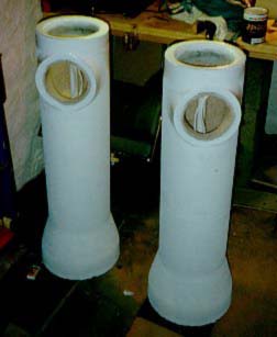
Speakers from the sewer All around the world, there are millions of them to be found, except in those areas completely untouched by civilisation. Forming gigantic networks whose only mission is to carry away whatever you decide to leave behind in your bathroom. Except two of them. You'll find them in my living room with a quite different mission of life -- playing music. I'm talking about the worlds most aristocratic sewage pipes. By Esben Beck, 27-Feb-97 It all started one Sunday afternoon about two years ago. I was out for a walk, and passing a construction area, I saw a pile of moulded concrete pipes. At that time, I was meditating a lot about alternative enclosure materials, so I decided to make a call to the local sewage pipe manufacturer the next day. After some confusing seconds during the introduction of my idea, they got sympathy for the project and gave me some information about density, wall thickness, diameter, weight, length etc. for their "most popular" models. After making a few calculations, I ended up buying two pressure-moulded, non-reinforced pipes. I paid about $10 each. But of course, feel free to use second hand pipes if my project inspires you. For some degree of hygiene, try to dig them up somewhere after the purification plant. The pipes measured as follows:
The pipes also had a wider joint section that would work well as a base for the
speakers. The joint section also proved an ideal separated enclosure for the crossover
network.
| ||||||||||||
 |
Preparing the pipes
Building these sewer pipe cabinets turned out to be a lot more complicated than building ordinary MDF cabinets. Due to this fact, I will try to describe the building process in detail, step by step. Hopefully, you will pick up a few tips and tricks if you decide to accomplish mine or a similar project. I recommend you to take a look at the cabinet drawing, which will make the article easier to understand. The manufacturer had the necessary equipment for drilling big holes in the pipes. And I was in bad need for big holes at this point, because the area needed for mounting the bass/midrange drivers were just a few centimetres smaller than the inner diameter of the pipe itself. In fact, the bass/midrange holes had to be as big as possible without any risk for cracks in the thin edges that would appear around them. They recommended a 178 mm (7") hole located with its periphery about 70 mm (2 3/4") from the edge of the pipe. Since the edges of the 178 mm drill had to be entered almost tangentially onto the inner diameter of the pipes, I had to ask the drill operator to be a little bit more accurate that he was used to, by telling him about how silly the speakers would look if he practised his normal sewage pipe tolerances. He did a very good job, and I was now the proud owner of the world's cheapest speaker cabinets ($10 each), but with the Milky Way's most expensive driver holes ($50 each). I decided to take out the bass port holes myself. | ||||||||||||
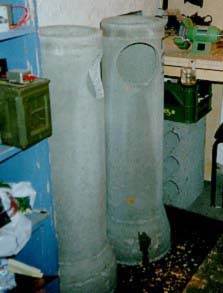 |
The pipes were
transported to my closet-sized workshop. Then I placed them on the floor, and for the
next 14 days, I just sat there staring at the pipes, worrying about where to begin,
while my circle of acquaintances worried about my mental condition. This is what I stared at for 14 days without getting
anywhere.
After the two weeks of brainwork, I decided to start working with the junction between the pipe and the baffle. In order to carry out a all-concrete concept, the junction had to be made from concrete too. A mould had to be made, and I decided to make it from a piece of vinyl floor covering. After making a supporting frame for the vinyl, I made a cupboard template for the outer vinyl sheet. I transferred the template pattern to the vinyl, and started to cut with a razor-sharp blade cutter. After only half a minute of work, the knife accidentally slipped. Luckily, I never achieve sexual excitement during speaker building, so the injury was limited to a small cut in my right groin. After returning from the casualty department, I completed the mould by cutting the vinyl sideways. Check out the result here. | ||||||||||||
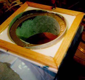 |
It is not possible to mould the
junction directly to the pipe, because it will not stick adequately. Therefore, the
junctions had to be removed from the pipes after hardening, and then be glued back on.
However, the junction concrete will stick quite good to the pipe, and in order to ease
the loosening of the junctions, the pipes were covered
with a thin plastic sheet before the moulds were filled. After 24 hours, the junction was hard enough to be removed from the mould,
and the second junction was made the same way. Each junction was moulded on its
respective pipe, in order to insure perfect matches.
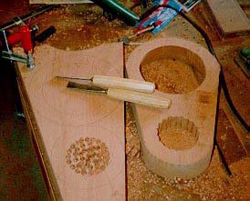
Concrete is supposed to harden under constant humid conditions over a period of at least 24 days. (I didn't have the patience required, so I glued them back on the tubes after keeping them in my drying closet for one week. More about this later). During the period waiting for the concrete junctions to harden, I continued working on the cabinets. First, I made the bass reflex holes. I used a Hilti hammer drill to perforate the circumference of the bass port hole, followed by some excellent craftsmanship using a hammer and a chisel. You might use a ordinary hammer drill, But I strongly recommend that you use a Hilti with its unique cushion hammer system due to the extreme hardness of non-reinforced concrete. The Hilti system also reduces the risk of cracks and shatterings. Ear protection during work like this is essential. I'm a true audiophile, and I intend to keep it that way for a while. The baffles, tops and terminal bases was cut out from a large 2 x 8" mahogany board, using a powerful jigsaw. The partition walls, subwoofer mounting ring and bottom plates were made from 22 mm MDF. Take a look at the baffles here, and the rest of the wood parts here. | ||||||||||||
 | |||||||||||||
| Assembly
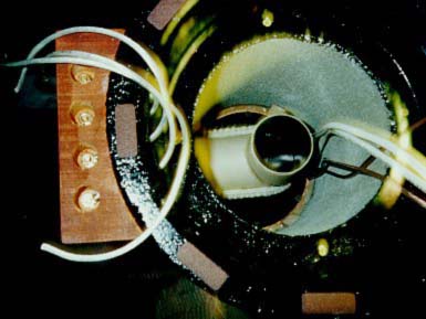
First, I mounted the internal rings for the woofers. The rings were fastened with
standard Araldit (epoxy-based glue to be mixed with hardener) that hardens within 24
hours. I also glued on a few plywood supporting wedges in order to obtain the best
possible hold without bolts. The mounting holes for the Scan-Speak 8545 and the holes
for the internal wiring had to be drilled before the ring was mounted, because it is
difficult to reach them inside the narrow pipe.
Then the 22 mm MDF partition wall between the bass/midrange enclosure and the CC-subwoofers' sealed enclosure was mounted. The partition wall was tilted in order to complete the cabinets' asymmetrical structures. The partition wall was also fastened with Araldit. In the centre of the partition wall, I mounted a oak rod to be connected to the top plate, in order to increase the rigidity. Even though the pipes were quite rigid at this point, they were making a ringing sound when I beat them with a hammer. The ringing was quite pure, indicating a dominant resonance peak that would be fatal. In order to reduce the resonance peak, I covered all internal surfaces (except the subwoofer's reflex chamber) with a thick floor carpet that had a viscous rubber base. The carpet was fastened with contact glue, and I spent a lot of effort insuring that every square millimetre of the carpet stuck well to the contact glue undercoating. The carpet successfully reduced the ringing to a insignificant level. I'll recommend you to use something else than contact glue, because it will introduce a quite intoxicating amount of vapourized formaldehyde in your living room while playing bass-heavy music for the first three weeks after gluing. | |||||||||||||
|
At this point, I
considered the moulded junctions hard enough to be glued back on. (I don't think they
were quite ready yet, but the successfull resonance killing made me so excited that my power of
judgement disappeared). I used huge amounts of Araldit for this purpose as well. In
order to test the Araldit joints after 24 hrs. of hardening, I unsuccessfully tried to
pull off the junctions with my hands. Then I used Plastic Padding to stop up the small
gaps between the junctions and the pipes. This picture
shows you the situation at that time. As you can see, it now for the first time felt
like I was getting somewhere.
The remaining works were routine. First, I primed the whole cabinets followed by two layers of black varnish. Then I mounted the Scan-Speak 8545 woofers, the bass ports and the terminals. Due to the narrowness of the pipes, I decided to avoid floor carpets in these sections, making it possible to replace the 8545's. Besides, these parts of the cabinets is only producing low frequency sound way below the resonance frequency of the concrete. The bass ports were squeezed into their holes, and the gaps around them were stopped up with non-sticky putty in order to make them removable. The terminals were fastened with wood screws and plastic expansion plugs, and so were the bottom plates with the crossover networks. Due to the high content of oil in mahogany, I could not use Araldit for mounting the mahogany baffles and tops. Instead, I used Sica-Flex, a seaming compound for naval purposes that sticks well to oil-containing types of wood like teak and mahogany. The black Sica-Flex also matched the varnish perfectly. The Seas G17RE-P bass/midrange unit and the H519 tweeter was finally mounted, and there they were -- the worlds' most aristocratic sewage pipes. Crossovers Phew... that's enough about concrete, glue and wood. What about the crossovers, phase linearity, frequency response and sensitivity ? And where are the units' waterfall plots, the on- and off axis response diagrams and the-impedance-magnitude-and-phase-versus-frequency diagrams?? Well, since there is nothing revolutionary about the driver configurations, I will not bother to write a long lecture about this. I think that some short descriptions will be content. | ||||||||||||
 |
The crossovers were originally
made to attain a three-way system, using a capacitor in series with the Seas G17RE-P.
I soon discovered that some energy was missing in the upper bass area. I decided to
remove the series capacitor, increasing the bass output from the Seas 6.5". Since the
6,5" has a closed cabinet, it will have a rolloff at 12 dB/octave. The crossover to
the 8545 is electrically a 6 dB filter with just a single series inductor, but the
coupled cavity-system forms a 12 dB lowpass response. Luckily, this matched the 12 dB
highpass rolloff for the Seas, and they summed into a quite flat response that worked
surprisingly well.
This is what my current 6/12/18 dB crossovers with the
RLC-circuit for the G17RE-P looks like. As you can see, there is nothing special about
it, so feel free to try your own crossover designs. The sensitivity of the speakers is
about 88dB.
Results
What more can I say? The speakers
turned out to be my best project so far, and the sound can be described as warm and
laid-back with a remarkable deep and precise bass caused by the excellent Scan-Speak
8545s' characteristics, and a very present midrange due to the Seas G17RE-P's
outstanding voice reproduction. The treble might seem a little bit "far away", not
responding so well to the "air" and the room information on my recordings, but it does
a good job, and it matches the rest of the sound characteristics of the speakers
without being persistent to my ears.
Late last year, the speakers were upgraded. The midrange and tweeter were replaced with a Seas Excel W17EX-001 and a Dynaudio Esotec D260, resulting in an even more precise and pure midrange, also producing a much deeper and wider sound stage. So, if you would like a pair of rigid, low-resonance speaker cabinets, I strongly recommend this concept.
Esben Beck |
