Records with musical information in the low bass does indeed become a physical experience with high quality subwoofers. Below 30 Hz, the physical impact, the FEEL of the low bass energy, is a lot more important than exactly hearing it. These subwoofers are able to reproduce the lowest note of a large church organ, which is 16.35 Hz. At this frequency, more than 100 dB is needed in order to hear anything, but the sound energy is sensed at considerably lower levels.
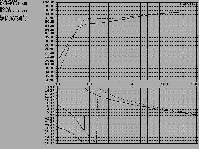
The solid line is without EQ, and the dotted is with 2nd order high-pass filter at 17 Hz with Q=1.25. The cut-off frequency 16 Hz is marked with a dot on the curve. With EQ there is essentially flat response in the sub-woofer frequency range. Some series resistance caused by cable resistance and amplifier output impedance is taken into account in these simulations.
Maximum SPL with 100W @ 8ohm input is simulated here:
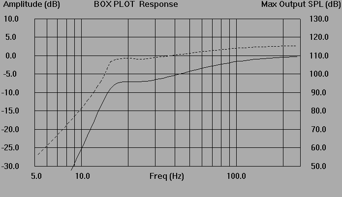
The system is capable of at least 108 dB SPL down to 16 Hz in free-field. A listening room is not free field, so higher SPL levels can be produced in a listening room.
The drivers are connected in parallell. This makes the system impedance to be 4 ohms nominal. A conjugate filter to equalize the impedance is recommended. The easiest way is to parallel the whole system with a 10-12 ohm high power resistor (at least a 20 watt). Use of L-C-R chains could give a more linear impedance, but the large component values needed make this a less attractive solution than just a resistor. A conjugate filter will unfortunately lower the overall impedance, but the goal of this arrangement is to reduce the impedance's phase shift. With most amplifiers, large phase shift is worse than a low and flat impedance. The impedance will reach down to 3 ohms with a 10 ohm parallell resistor.
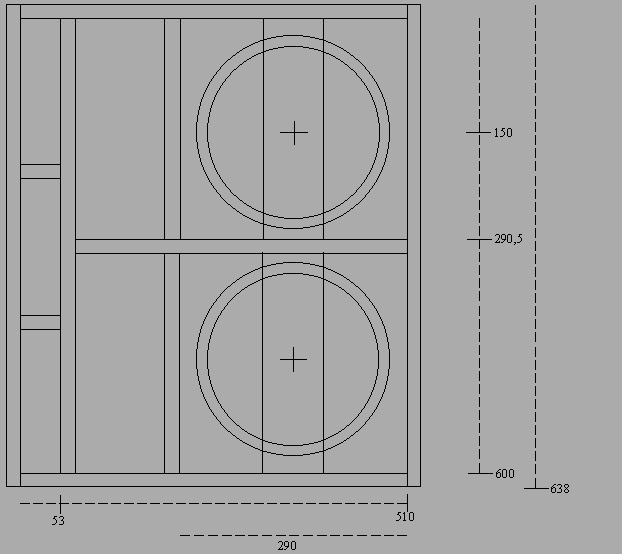
Box side view:
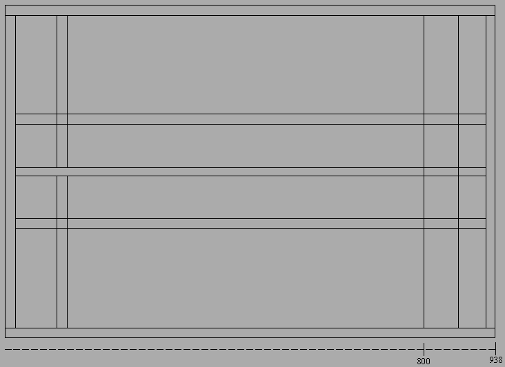
Box top view:
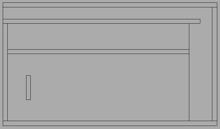
Parts list, all 19 mm HDF
| Side walls | 957 x 638 mm, 2 pcs |
| Top and bottom | 957 x 510 mm, 2 pcs |
| Inner port wall | 866 x 600 mm, 1 pcs |
| Inner horizontal | 491 x 800 mm, 1 pcs |
| Inner verticals | 290,5 x 800 mm, 2 pcs |
| Driver support piece | 290,5 x 80 mm, 2 pcs |
| Spacers inside port | 53 x 938 mm, 2 pcs |
I recommend building the boxes in 19 mm High Density Fiberboard (HDF). There is no point in building them more rigid than shown in my original plans, at least if you have no intentions of crossing higher than 80 Hz. Low frequencies have too long wavelengths to put the box walls or the air inside the box into resonance. The lowest modal resonance inside the box will be at about 190 Hz. A high crossover frequency will need a more resonance-free box, since these higher frequencies really can make the box walls sing! With exclusive sub-woofer use though (a low crossover frequency), the vibration level of this box is remarkably low. High mass is very important to keep the box stand still at high levels (spikes don't help much). Built in 19 mm HDF the original box weighs about 75 kg. This is less than optimum, so you should consider placing some heavy object on the top of the box to increase its weight. I've tripled the weight of my own subwoofers by adding 150 kg of amplifiers on top. This really a had good effect.
This box design reduces nonsymmetric acoustic load on the drivers' cones. This is done by mounting them at the end of a long symmetric tunnel, which to some extend protect them from the very powerful load from the port inside the box. The pressure which the port resonance creates inside the box is strongest at the port end. This pressure is distributed more uniform across the drivers' cones with this arrangement, which in turn makes the drivers operate in a more linear fashion.
A comment about the support piece for the drivers' magnets is also necessary. This piece is very important in order to get tight and uncolored bass. It 'drains' resonances from the driver's chassis, and makes it impossible for the driver's magnets (and chassis) to actually move the opposite direction of the voice coil, which it will without this support piece. It must be perfectly aligned so that it makes tight contact with the driver's magnet.
The box should be about 50% filled up with loosely packed fiberglass (building insulation). Leave free space near the end of the port. Do not obstruct the inner end of the port, nor the port itself.
From a modal resonance point of view, box damping should not be necessary, since modal resonances inside the box cannot exist below 190 Hz. However, fiberglass filling will increase the acoustical volume of the box slightly, and damp mechanical noises from the drivers. Sound coming from outside the box will also create audible reverberation inside the box if it's left undamped.
If you like to design your own box, please remember that a large port area is very important to minimize compression. The port area used in my box plans (about 300 sq. cm) is what I consider an absolute minimum. A large port area results in a very long port, so an alternative box design is restricted by the need for great port length. The port should not be folded or bent.
High quality speaker wire is as important in a subwoofer as everywhere else. Use good quality solid-core wires. Stay away from multi-stranded wire. I can happily recommend the Flatline cable. This is the most 'honest' cable I know, especially the bass is superb.
Since these drivers were a custom model, they will unfortunately not be made anymore. To match their quality, it is needed to look for something really special as replacement. The brand new ScanSpeak 25W8565-01 is an excellent choice. It has different parameters than the 25W7564, but in this box the differences in frequency response will be less than +/-1 dB in the whole 15-100 Hz range. Therefore it is no danger to regard the 25W8565-01 as an equivalent driver (in this system, not necessarily in other boxes). It will even have higher max. SPL than 25W7564 (with higher input, though), partly because of a longer voice coil and slightly larger cone area.
The very satisfying sound quality from my sub-woofers is to a large extend a result of the outstanding quality of these custom drivers. Special features includes very stiff and rigid carbon fiber filled paper cone, diecast magnesium chassis, double spider, low-loss rubber surround and vented magnet system. They were designed with subwoofers in mind, and are not recommended for use above 150 Hz. The same attributes are valid for the 25W8565-01, except for the double spider. The 25W8565-01's cone is even stiffer than on the 25W7564.
ScanSpeak 25W7564 driver parameters:
The Extended Bass Shelf alignment relies on some EQ to obtain a reasonably flat response. Since active filtering is the only practical solution for crossover networks at low frequencies, it is simply to add another filter circuit in the active crossover to do the necessary EQ. A 2nd order high-pass filter with a Q higher than 1 will EQ the low end, and at the same time make an effective subsonic filter (absolutely necessary when playing LP's!). I recommend a 2nd order filter at 17 Hz with Q=1.25 (see the curves). The crossover should be at least 4th order, or more (I use 6th order). A steep crossover will make it a lot easier to integrate the sound of the subwoofers with the main system. Everyone I know who have experimented with active crossovers, concluded that the steeper slope, the better sound. A 4th order filter is easily made with two stages of 'op-amp' active 2nd order filters (which of course could be any kind of amp, not necessarily an op-amp chip). I use the LM837 quadruple op-amp chip for my own filters. See some kind of 'active filters cookbook' for details about designing active filters.
I resist giving specific filter plans, as those will be dependent on what main system you will use. Crossover frequency, level, phase etc. should absolutely be matched to the main system. There is unfortunately no 'quick-fix' to use that will give 100% satisfying results.
One solution which I use myself, is to let the subwoofer system continue from the point where the main system has it's natural cut-off. In my case the main system cuts off with 6th order slope, -6 dB at 32 Hz. Therefore I use 6th order filters that acts like (more on this later) filters with Q=0.5 at 32Hz for the sub's, and no filtering for the main system. The main system and the sub will then have the same slope, same Q, same -6 dB point, and the same phase shift (180 degrees) at the crossover frequency. This gives a flat summed response and well behaved phase response. Although this works well in my system, some degree of filtering of the main system is recommended. Most speakers will be happy to get rid of the low bass.
An other example: The main system is a closed box, a box type which have 2nd order cut-off. The -3 dB point is at 60 Hz. We can then choose to cross at 60 Hz, and build a 2nd order filter at 60 Hz with Q=0,7 (-3 dB at 60 Hz) for the main system. This makes the main system fall off 4th order from the -6 dB point at 60 Hz. The subs must then be filtered with the same slope to get a flat summed response, meaning a 4th order filter at 60 Hz, with total Q of 0,5 (two filter stages with Q=0,7).
The two examples shown above will work perfectly if the loudspeaker box itself has no phase shift at the desired crossover frequency. This is never the case. A crossover which shifts the phase 180 degrees, will not make the whole system shift the same, because the loudspeaker box's own phase shift is added to the total phase response. In addition the EQ filter also shifts the phase. It is therefore necessary to alter the crossover frequency and Q of the filter in order to get the desired 180 degrees phase shift at the crossover frequency. An analysis of this is very impractical to do by hand, only a speaker crossover CAD system can do this effectively. I use CALSOD for my simulations.
These problems can be avoided to some extend by using 4th order or steeper filters, and by placing the crossover point well above the main speakers' cut-off and in a region where the sub's have low phase shift. This means a crossover frequency around 100-150 Hz. However, crossing that high is a compromised solution.
Level control must also be implemented in the filter electronics. It will most certainly be differences in sensitivity between the main loudspeaker system and the subwoofers, and between the amplifiers.
All this may seem difficult, but it is absolutely necessary to do a thorough investigation of the whole concept to get the desired result. Most subwoofer systems do not at all sound integrated in the total soundstage, mostly because of inferior filters. Remember this!
My subwoofers are intended to radiate directly towards the listener, and they should be time-aligned with the main system. The depth of the box makes it possible to stack them close up to the front wall. They are also intended to stand on the floor, even if a placement free from the floor theoretically is better. The size and proportions of the box makes this a little less attractive. I use my subwoofers as a table to place all my power amplifiers! My own sub's are placed between the main speakers (these are floor-standing types), close to each main speaker. Smaller main speakers should be placed on the top of each according subwoofer.
Listening room acoustics is mostly a sad story, especially in small rooms. Standing waves at low frequencies are very prominent in acoustically untreated rooms, and this will of course degrade the performance of a well designed loudspeaker system. An other anomality is that the lowest bass can be fully enjoyed only in the opposite end of the room. Installation of a high quality loudspeaker system may well display that the room acoustics are less than perfect......
Comments, questions etc... mail to stig.e.tangen@no.ibm.com
I will NOT repond to questions regarding general crossover or box design!
For you Norwegians.....
Det er mulig å få hørt systemet, hvis du er veldig interessert. Jeg bor ca. 1,5 time nord for Oslo.